TEXTILES.ORG
 Creating a virtual bimini
Last summer we created a “virtual” three-bow bimini frame and top from measurements taken using CAD. A 3-D bimini is modeled in CAD software using measurements taken in the field. The frame is dimensioned for specs necessary to bend the tubing. The top, created by “flattening” its 3-D surfaces to a 2-D plane, is cut by the plotter/cutter.
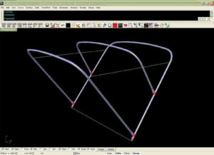
This shows the bows after crowning, filleting the corners and extruding the pipe. The green lines along the sides represent the edge of the finished top.
First, measurements that define the finished bimini are recorded on paper. These dimensions measure the height of the frame, coverage of the top, and the widths at mount and shoulder of the main bow. The tubing size, fittings and custom details are noted. The crown and radii are determined using formulas based on proper bimini geometry.
The initial measurements are entered into CAD software and are used to create a box that defines the finished bimini. The width, length and height of the box reflect the width, length and height of the finished bimini. The width of the box measures the width of the beam, the length measures the coverage of the top, and the height measures the height of the frame. A bimini with a shoulder width narrower than its mount width produces a box that narrows from bottom to top.
On the computer, the main bow is drawn in side view from the top right corner of the box past the middle of the bottom line. It is drawn off center for the bows to stay even when stacked. The main bow is mirrored from the middle of the bottom line to produce the secondary bow, and is then used to trim off the excess. A line drawn two inches above the center of the top line references the edge of the float bow, which is created by mirroring the main bow from its midpoint.
Switching to 3-D view in CAD, we mirror the bows to the other side of the box. Straight lines drawn to connect the top edges of the bows are copied down with the distance of the crown height. These lines are used as reference points for the arcs drawn to make the crowns. Using documented measurements derived from reverse engineering the tubing bent by our shop benders, the crowns and bows are filleted together to create the shoulder radii.

The digital image of the top is “peeled” to show a flat construction plane.
The next step involves using fittings to trim the bows. Jaw slides, eye ends, deck hinges and other fittings of standard and custom sizes have been modeled with our CAD software. The fittings are imported into the computer drawing, oriented to fit the bows, and used to trim the bows to their final size. We use the software to combine the top edges of the pipe to create the top of the bimini. The model is complete.
The computer files of the bows and a 2-D pattern of the top are divided into map and plot functions. The bows are offset to actual dimensions, marked with bend lines, exported to the plotter, and are drawn on Canvex. Hems, pockets and seam allowances are added to the top, which is then sent to the cutter to be cut out of fabric. Maps describing the construction of the bimini are given to the seamstress and the pipe benders.
A virtual bimini takes no more than an hour to make. With practice, that time can be cut in half. While a virtual bimini cuts down considerable time and labor, its real virtues lie in making a physical pattern unnecessary, making the top exactly fit the frame, making the frame specs exactly suit our shop benders, and making the bimini a repeatable job in the future.
Greg Fadeev is the CAD department manager of Canvas Designers Inc.