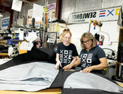
Fabricating with CAD technology
Letting technology work for you can lead to increased efficiency and increased profits.
By Greg Fadeev, Canvas Designers Inc.
Technology can be scary. But because you run a custom marine fabrication shop you should consider the possibilities and the potential of digitizing your patterning processes and automating your cutting processes. A reputable vendor will be able to assess your probable return on investment for software and hardware acquisitions.
The ROI on a technology purchase depends in part on the type of work you do and the amount of materials you use. Small fabricators that do complex work with expensive materials can gain as many benefits as large manufacturers that use inexpensive materials.
Before you start counting dollar bills, it’s important to understand how this stuff works. To explain the technology and how it can benefit your business, Marine Fabricator asked Greg Fadeev, CAD department manager, Canvas Designers Inc., Riviera Beach, Fla., to discuss the equipment and processes his team uses in the shop.
Canvas Designers has been “digital” for three-and-a-half years. Utilization of the technology has produced double-digit increases in both efficiency and profitability.
Computer aided design (CAD) tools
At Canvas Designers, we use a Proliner 3-D digitizer by Prodim USA. The Proliner transforms objects into digital images. The device measures X, Y and Z coordinates by using measuring points that are input by the fabricator. Rendered objects lie on a flat plane, like most canvas patterns, or stand in 3-D, like the helm on a 74-foot Viking Sport Fisher.
A “pen” wired to a rotating head measures the Z axis, and the rotating head measures the X and Y axes. To measure an object, the fabricator places the pen on relevant points on the object and clicks a button on a handheld remote control. The Proliner automatically connects these points, transforming them into shapes, which are then stored as digital CAD files.
Canvas Designers uses the Proliner to measure Canvex patterns in the field, although our experiments with 3-D imaging have been uncommonly successful. But because we have three field crews to one imager, it is more cost effective to bring patterns into the shop than to take the machine out.
Features of the Proliner
- Accurate to 1⁄16 inch
- Stores files on a portable drive
- Simple CAD functions help verify measurements on site
- Touchscreen allows easy input of information and immediate views of measurements
- Measurements are saved as DXF (digital exchange files), the most commonly shared file types by CAD software
- Device measures from the horizontal and vertical positions, upside-down, and fastens to a tripod. It is small, light and self contained
- Allows the measuring of objects that would otherwise be out of range using “Leap Frog” method with four hockey-puck-shaped discs as reference points that connect one drawing to the next
We use Rhino CAD software. Common to quality CAD software are various tools and commands that perform predefined tasks when accessed by the keyboard or mouse on a desktop computer. These tools effectively replace their manual counterparts, surpassing them in speed, accuracy and efficiency.
To draw a line by hand, one would place a pencil along a straight edge on drawing material and mark the desired length. To draw a line using Rhino, one would type in “l” followed by its length. What can be designed using traditional methods is more quickly and precisely designed using CAD software.
The tools in Rhino are customizable to suit the needs of a job. This feature is especially useful when designing the same type of product repeatedly. We’ve found that toolbars, which we create to act as shortcuts to frequently used commands, help get over the learning curve of CAD software.
We use Rhino to process and export to our automated cutter/plotter patterns imported from the Proliner. The software creates detailed spec sheets with every job, designs new products, prototypes existing products, models virtual biminis, and creates templates that form the standards that guide our building processes.
Features of Rhino
- View models from any angle
- Intuitive layout, easily learned commands, dynamic pan and zoom
- 3-D modeling to scale using surfaces; flattens surfaces to produce flat patterns
- Imports and shares files with other software and the Proliner; exports to other software and cutter/plotter
- Accurate to 1⁄64 inch
- Price, relative to other CAD software
We use a Carlson plotter/cutter to cut parts, draw glass and make templates. The plotter is run by Plotmaster (PM) software loaded onto a desktop computer. Plotmaster translates files imported from Rhino into plot paths for the plotter to follow. An individual plot path derives from a CAD file that “nests” patterns on to the cutter to allow for the best use of fabric.
Once a plot is chosen, two motors drive the plotter forward along tracks atop a 32-foot by 80-inch table, while a pneumatically controlled pen and blade assembly draws and cuts the pattern.
The cutting surface lies on top of a series of holes. When preparing to cut parts, fabric is unrolled and suctioned to the table using vacuums. The suction is also helpful when imaging with the Proliner on Canvex.
Features of cutter/plotter
- Accurate to 1⁄16 inch
- Shares files commonly used by other CAD software
- A handheld button attached to the workstation manipulates the plotter when clicked and allows user to pause a plot, stop a plot or return the plotter back to the beginning of the plot
2-D patterning
Rigid enclosures best illustrate the advantages of using CAD over traditional methods. Before CAD, Canvex patterns made by field technicians were manually processed on a work bench in the shop. A pattern was pinned to a table and marked, inch by inch and panel by panel, using colored markers, straight edges and curved rulers. This process took between four and six hours.
The pattern was then pinned over fabric, where the borders and fold and seam allowances were transferred by hand with the aid of tracing paper, and then cut out. This took about six hours. The final step was to transfer the cut lines onto the rigid glass with a marker. This took about an hour.
Now, we cut every rigid enclosure using CAD equipment. Enclosures, or any jobs involving physical patterns, typically go through the same process: The digitized pattern is refined in Rhino, exported by Rhino to Plotmaster, and cut with the plotter/cutter. The original pattern is taped and suctioned to the vacuum table, and then is digitized with the Proliner. The digitized files are downloaded from the digitizer to the CAD workstation. The files are then imported into Rhino CAD software, where they are oriented together to form the entire enclosure.
Working with a 1⁄32-inch tolerance, the track and zipper lines are traced over with cleaner, fairer curves, and offset using our custom toolbars to create the borders and shape the glass. Final customizations are added before dividing the enclosure into separate files consisting of parts and glass.
The digital parts and glass files are labeled and nested—for best material use—on fabric and glass rectangles. These nested files are then exported to the plotter/cutter. The cut parts and drawn glass (along with a spec sheet) are delivered to the rigid enclosure department that sews the parts, cuts the glass and builds the finished enclosure.
The entire process, from taping the pattern to the table to delivering the glass, takes about three hours. Using the software, one person does the job more accurately in a quarter of the time than with traditional methods.
Standards
Since building a product from parts cut by CAD no longer requires a fabricator to work directly from a pattern, the necessary design specs formerly delineated by the pattern have been replaced by printed paper templates called “maps.” These maps detail the components and describe the assembly of each product, and accompany each job to assist construction.
Similar types of jobs typically have similar design specs, which allow each project to have similar standards in design and procedure. We have developed standards for all products, not only to ensure quality and efficiency in construction, but to reduce time, labor and materials, as well as to reduce errors caused by lack of information.
3-D innovation
The 3-D digitizer effectively replaces physical patterning methods. To test its patterning effectiveness, we used our Proliner to image the track lines for an enclosure on the bridge of a 74-foot Viking Sport Fish.
We imaged both tracks and the zipper lines in three phases, linking each drawing to the next by means of shared reference points. The files were then uploaded to the CAD workstation and imported into Rhino software that formed the enclosure in 3-D. The software flattened the 3-D panels into a 2-D image, and then made the image into a pattern. The pattern was processed and built.
Keep in mind that every purchase must have a clear justification. If inefficiencies in production are impeding your processes and costing your shop money in lost time, lost materials or lost business, then it makes sense to look at technology options to fix those problems, as long as the improvements will pay for themselves relatively quickly.
Granted, the price for these high-end technologies is probably more than most small shops will want to take on; however, there’s no harm in investigating the possibilities. Just as the discovery of electricity propelled the second Industrial Revolution, CAD technology has revolutionized the marine fabrication industry—and can revolutionize your efficiency and your bottom line.
Greg Fadeev is the CAD department manager of Canvas Designers Inc.
Manual vs. automated
Five-panel, three-sided rigid enclosure for a 74-foot Viking
Manual
Process pattern: 6 hrs.
Cut parts and draw glass: 6 hrs.
Total: 12 hrs.
Automated
Process pattern: 1 hr.
Process parts and glass: 30 min.
Cut parts and draw glass: 1 hr.
Total: 2 hrs. 30 min.
Three bow bimini for a 13-foot Boston Whaler
Manual
Measure: 10 min.
Build frame: 45 min.
Strap and fit: 90 min.
Cut top: 60 min.
Total: 3 hrs. 25 min.
Automated
Measure: 10 min.
Model and map: 20 min.
Build frame: 45 min.
Cut top: 10 min.
Total: 1 hr. 25 min.
Cockpit cover for a 60-foot Viking
Manual
Measure: 30 min.
Layout on fabric: 1 hr.
Cut: 15 min.
Total: 1 hr. 45 min.
Automated
Measure: 30 min.
Map: 10 min.
Cut: 10 min.
Total: 50 min.
Benefits of technology
- Set standards in quality and precision
- Patterns need to be taken only once
- Patterns, once taken, are repeatable
- Plotter cuts job while CAD operator works on another
- Pattern in the wind and/or rain
- Patterns are easily correctable
- Time and materials, once tracked, can be repeated
- Paper maps cost less than Canvex patterns
- No need to store physical patterns
- Thousandths-of-an-inch accuracy
- Outsource CAD services
- Save material loss with efficient nesting
 TEXTILES.ORG


